
Which geometric parameters influence the radar backscatter?
The Earth’s surface is a complex target. Multiple parameters play a significant role in the strength of the radar echoes as they are received by the SAR sensor. This strength of the returning signal is referred to as backscatter intensity. So-called ‘ground parameters‘ comprise those variables that describe the composition of objects on the Earth’s surface and influence the backscatter intensity drastically are given below:
- Topography
- Surface roughness
- Object geometry
- Object orientation
- Dielectric constant (or water content).
for Colours Palate:
- e1e8ea
- f2f2f2
- f1f0de
- ece6e6
- d9dfd9
- f1ede8
- e3ecec
Video Title

By loading the video, you agree to YouTube’s privacy policy.
Learn more
Single-pol
Transmits horizontally or vertically polarized waveforms and receives it in the same direction. The naming convention would be HH (Horizontal, Horizontal) or VV (Vertical, Vertical).
Example:
ERS-1, Radarsat-1
Single-pol
Transmits horizontally or vertically polarized waveforms and receives it in the same direction. The naming convention would be HH (Horizontal, Horizontal) or VV (Vertical, Vertical).
Example:
ERS-1, Radarsat-1
Single-pol
Transmits horizontally or vertically polarized waveforms and receives it in the same direction. The naming convention would be HH (Horizontal, Horizontal) or VV (Vertical, Vertical).
Example:
ERS-1, Radarsat-1
dual-pol
Transmits horizontally or vertically polarized waveforms and receives it in the same direction. The naming convention would be HH (Horizontal, Horizontal) or VV (Vertical, Vertical).
Example:
ERS-1, Radarsat-1
quad-pol
Transmits horizontally or vertically polarized waveforms and receives it in the same direction. The naming convention would be HH (Horizontal, Horizontal) or VV (Vertical, Vertical).
Example:
ERS-1, Radarsat-1
Linear polarisation
This is the most common polarisation technique for spaceborne radar systems. Here, the electric field of light is confined to a single plane along the direction of propagation as given on the right.
Linear polarisation
This is the most common polarisation technique for spaceborne radar systems. Here, the electric field of light is confined to a single plane along the direction of propagation as given on the right.
Linear polarisation
This is the most common polarisation technique for spaceborne radar systems. Here, the electric field of light is confined to a single plane along the direction of propagation as given on the right.
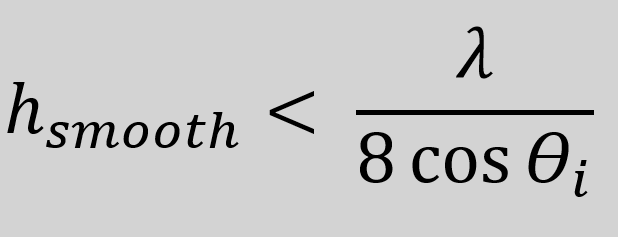
The Rayleigh criterion
This criterion was defined by the British scientist John W. Strutt and is widely used for the specification of the minimum separation between a smooth and rough surface. It states that a smooth surface, is characterized by a phase difference due to h that is less than 1/4 of a wavelength (e.g. for C-Band = 6 cm).
If the change of phase would exceed this threshold, scattered radiation would not be coherent (on average) and therefore scattered waves become more diffuse. The definition of a smooth surface hsmooth is given on the right.
The factor 8 by which this term is divided arises from the two-way path the emitted energy has to take to reach the sensor again after being scattered.
λ represents the wavelength of the incoming radiation and θ the incidence angle. Latter, influences the path difference the is associated with the surface roughness.

Source: Nave (2005).
Swath
The term ‘swath’ has its roots in farming. It describes the width of a scythe. This analogy has been transferred into remote sensing. In this context, the swath width describes the area (width) on the ground that is covered by the sensor instrument of satellites or aircrafts.
In the context of radar, the swath describes the strip of the Earth’s surface that is illuminated by the radar. The swath has a longitudinal extent, which corresponds to the movement of the sensor in azimuth direction. The swath width is the respective perpendicular component in range direction.
Azimuth
In the context of radar remote sensing, azimuth describes the flight direction or direction of travel of the satellite/aircraft. It can also be referred to as the line of flight.
In an image, azimuth is also known as along-track direction, since it is the relative along-track position of an object within the antenna’s field of view following the radar’s line of flight.
source: hyperlink
How are wavelength and frequency related?
Wavelength and frequency of microwave radiation have a close relationship and are consequently depending on each other. Electromagnetic waves travel at the speed of light (299,792 km/s). As shown above, there are many different types of waves with varying frequencies and wavelengths.
They are all related by one important equation: Any electromagnetic wave’s frequency (f) multiplied by its wavelength (λ) equals the speed of light (c).
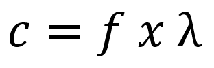
Following, this relationship can be used to figure out the wavelength or frequency of any microwave if the other variable is known.
Multi-looking
The first option to reduce speckle is the process of multi-looking. Here, observation of the same target are averaged to smooth out speckle effects. The so-called ‘looks‘ basically represent smaller sub-apertures of the original aperture, which are averaged and processed separately. However, the factor at which the speckle variance is reduced within the data relates to a loss in spatial resolution as well. Therefore, multi-looking is always a trade-off between spatial detail and minimization of grey level variations as you can see in the figures below.


Viewing Geometry
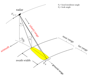
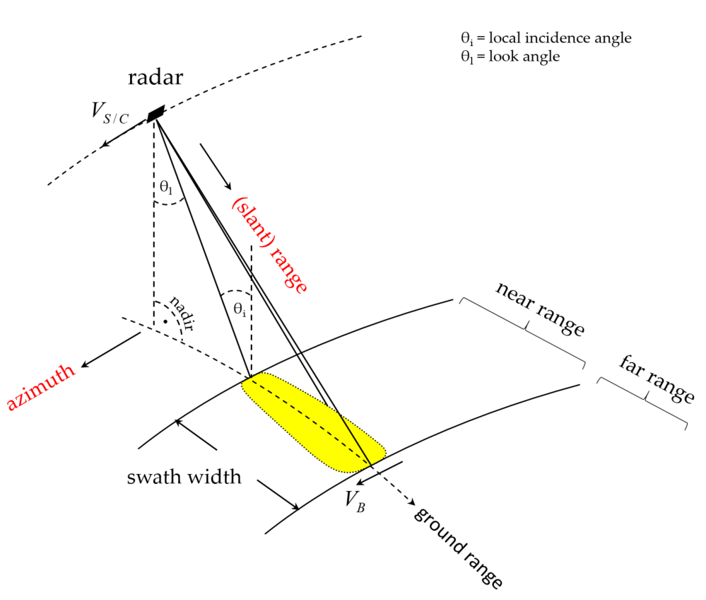
Viewing Geometry
Second line
Source: Small (2011).
Backscatter variables and their reference areas
- β0 – slant range plane
- σ0 – ground modelled using an ellipsoidal Earth surface
- γ0 – plane perpendicular to the local look direction
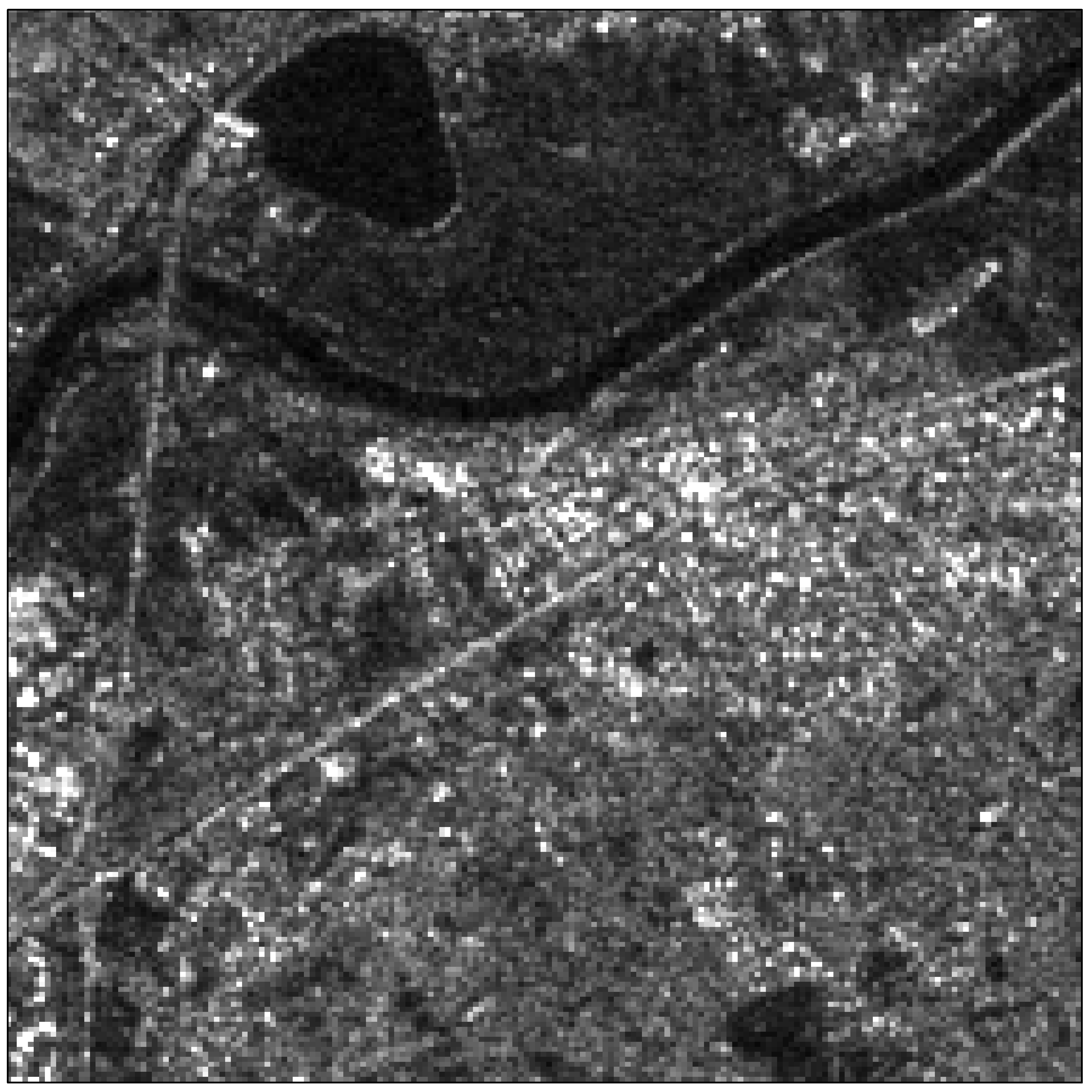
Explore the hotspots in the image to obtain a glimpse of the radar imaging effects.
Click on the individual Icons to learn more. Use the full screen mode () on the image to get the best learning experience.
Field scenario
Next Topic:
The radar equation
With this introduction you learned how different backscatter mechanisms depend on wavelength and target geometry. Now let’s move on to the next topic, the notorious radar equation.
Click the ‘Submit’ Button on the right to rate this topic and then move on to the next topic.